Before You Go, Get a Free Technical Proposal
Our senior engineers will prepare a customized proposal based on your initial requirements, covering product selection, key technical points, and an integration plan. Get valuable insights in minutes.
In the field of precision measurement, the Wheatstone bridge is a fundamental circuit used to convert minute resistance changes into a measurable voltage signal. This technical document details the bridge wiring for four 3-wire sensors (e.g., load cells), illustrating the working principle and practical applications to provide a clear technical reference for developers designing high-precision measurement systems.
In the field of precision measurement, the Wheatstone Bridge is a foundational core circuit used to convert minute resistance changes from a sensor into a measurable voltage signal. By correctly wiring four 3-wire sensors (such as strain gauge-based load cells) into a full-bridge circuit, one can achieve high-precision, high-stability measurements of physical quantities like force, pressure, and weight.
This document provides a detailed diagram and explanation of the bridge wiring for four 3-wire sensors.
A standard Wheatstone bridge consists of four resistive arms arranged in a diamond-like structure. Two opposite nodes are connected to an excitation voltage (V+ and V-), while the other two nodes serve as the differential signal output (Vout+ and Vout-). When the resistance of all four arms is equal, the bridge is “balanced,” and the output voltage is zero. If the resistance of one or more arms changes due to an external physical quantity, the bridge becomes “unbalanced,” producing a small voltage difference at the output terminals that is proportional to the change in resistance.
A 3-wire sensor typically includes the following leads:
Compared to a 2-wire setup, the 3-wire configuration separates the power supply and signal lines, effectively reducing the impact of power supply noise on the signal and ensuring greater stability and accuracy.
To construct a full-bridge circuit, the four 3-wire sensors must be connected as shown in the diagram below.
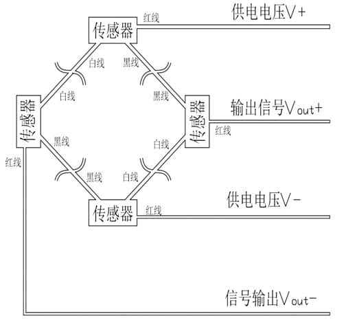
Detailed Wiring Steps:
When the excitation voltage is applied and no force is acting on the sensors (i.e., their resistances are equal), the bridge is balanced, the potentials at Vout+ and Vout- are equal, and the voltage difference is zero. When a weight or pressure is applied, the resistance of the internal strain gauges changes, unbalancing the bridge. This creates a microvolt or millivolt-level voltage difference between Vout+ and Vout-, which can be amplified and processed to precisely calculate the measured physical quantity.
Understanding and correctly constructing a Wheatstone bridge is the first step in developing any high-precision measurement device, especially in the fields of weighing systems and body composition analysis. A firm grasp of these fundamental principles is one of the core philosophies behind iBodyinfo’s design and manufacturing of high-precision BIA measurement modules and serves as the cornerstone for ensuring our products’ exceptional performance and data reliability.